Setting up an Adapter for a Wii Controller
This guide walks through the hardware and software setup required to use a Wii controller extension with Santroller.
Supplies
Required
-
Microcontroller
- Pi Pico 1, Pi Pico 2, or microcontrollers based on them are currently the only supported options.
- Previous versions of Santroller supported additional microcontrollers; information about those can be found below.
Legacy microcontrollers
- The following microcontrollers are only supported by v10.1.188. They are no longer supported by recent versions of Santroller, and bug fixes and features from newer versions of Santroller will not be ported to them.
- Sparkfun Pro Micro (5v)
- The 5V Pro Micro will work fine for direct wiring, but being that it runs at 5V, it will require voltage conversion to build Wii adapters and PS2 adapters and turntables.
- Sparkfun Pro Micro (3.3v)
- If you want to build an adapter for a Wii or PS2 guitar, this will be easier to use than any of the 5V microcontrollers. Due to the lower voltage, these do run at half the speed of the 5v variants, a. Clones of the Pro Micro are quite cheap but will need to be purchased from eBay or AliExpress, real Pro Micros are expensive, but there isn't much of a difference. 3.3V arduinos will poll a Wii guitar slightly slower than a 5V Arduino but in practice this doesn't end up being important as there are a lot of other delays involved when communicating with a Wii guitar.
- Arduino Micro
- This is essentially the same thing as a Pro Micro 5V, except that it is officially made by Arduino. This causes it to be more expensive compared to a Raspberry Pi Pico.
- Arduino Leonardo
- The Arduino Leonardo is essentially a 5V Pro Micro, except it has the layout of an Arduino Uno. You can find clones of these, but they are still more expensive then a Pro Micro or a Raspberry Pi Pico.
- Arduino Uno (r1/r2/r3)
- The Arduino R1, R2, and R3 controllers are actually two microcontrollers in one, and they work in tandem to provide a working controller. This has its disadvantages, as code needs to keep these controllers in sync, and this can result in issues if a bad configuration is programmed, and generally results in requiring more complicated and optimised code to work. Unos do still get 1000hz, but if you are buying a new microcontroller, we recommend against purchasing them. Note that some clone Arduino Unos are actually missing the second microcontroller, and these ones will NOT work at all. If you see an Arduino Uno listing that mentions "ch340g" or something similar, do not purchase it. Due to this, they are harder to purchase and since they require more parts, they are more expensive than a Pro Micro or Pi Pico.
- Arduino Mega 2560
- These are in the same situation as the Uno, however the main microcontroller has a lot more pins. They also end up being more expensive due to the amount of parts that are needed to make one.
- Sparkfun Pro Micro (5v)
- Incompatible microcontrollers
- Arduino Uno R4
- This is the latest entry to the Arduino Uno line of products. The Arduino Uno R4 is unsupported due to using a different microcontroller.
- Arduino Mini or Nano or Pro Mini or Pro Nano
- These do NOT work, as they are essentially Unos that lack the second micro controller that allow for custom USB device emulation.
- ESP32
- Currently this is not supported due to the base ESP32 not fully supporting USB. There are some ESP32 models that have USB support, but these end up being more expensive than the Pi Pico, and thus it does not make sense to support these.
- Arduino Uno R4
-
Wii Extension breakout board or extension cable
- Example: Adafruit Wii Nunchuck Breakout Adapter
- You may also cut the end off an extension cable and solder directly if preferred
-
Wire
-
Soldering iron
Power considerations
- If your Wii Extension breakout does not support 3.3V input and you are using a 5V microcontroller, you will need a 3.3V voltage regulator
- The Adafruit breakout linked above supports both 3.3V and 5V input and does not require an external regulator
Optional features
Tilt support
Any of the following options are supported:
-
Digital tilt switch (sometimes called a mercury or ball tilt switch)
- Using two tilt switches in series is recommended to reduce accidental activations
-
Digital accelerometers: ADXL345 or LIS3DH
- Provides analog acceleration data
- Tilt is detected using acceleration due to gravity
- While the MPU-6050 is supported, it has been obselete for years now, and thus most MPU-6050s that can be purchased are fakes and the fake units have many issues, so it is recommended to stay away from them.
-
Analog accelerometers: ADXL335 or accelerometers found in some Guitar Hero guitars
- Provides analog acceleration data
- Tilt is detected using acceleration due to gravity
Never supply 5V power to the power pin of a Wii Extension. Wii Extensions are not designed for 5V input.
The data pins are 5V tolerant and may be connected directly to microcontroller GPIO pins.
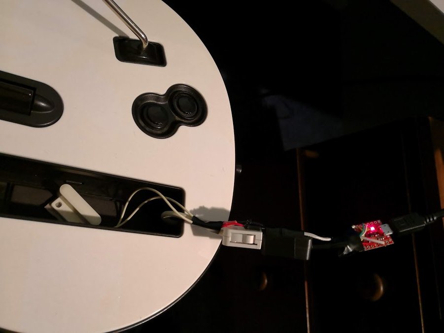
Finished product
Wiring steps
1. Connect SDA and SCL
Connect the SDA and SCL pins from your Wii Extension breakout or extension cable to your microcontroller.
Refer to the image below for the Wii Extension connector pinout.
The Pi Pico allows multiple pin choices for SDA and SCL. Recommended pins are listed below and match the legacy Ardwiino firmware layout. If using different pins, both SDA and SCL must be from the same I²C channel.
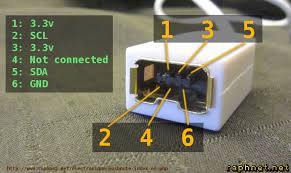
If you are using a Wii Extension cable, do NOT rely on wire colors.
Manufacturers use inconsistent coloring. Always verify each wire using the pinout above. Some cables have been observed with green as ground and black as 3.3V.
| Microcontroller | SDA | SCL |
|---|---|---|
| Pi Pico (Recommended) | GP18 | GP19 |
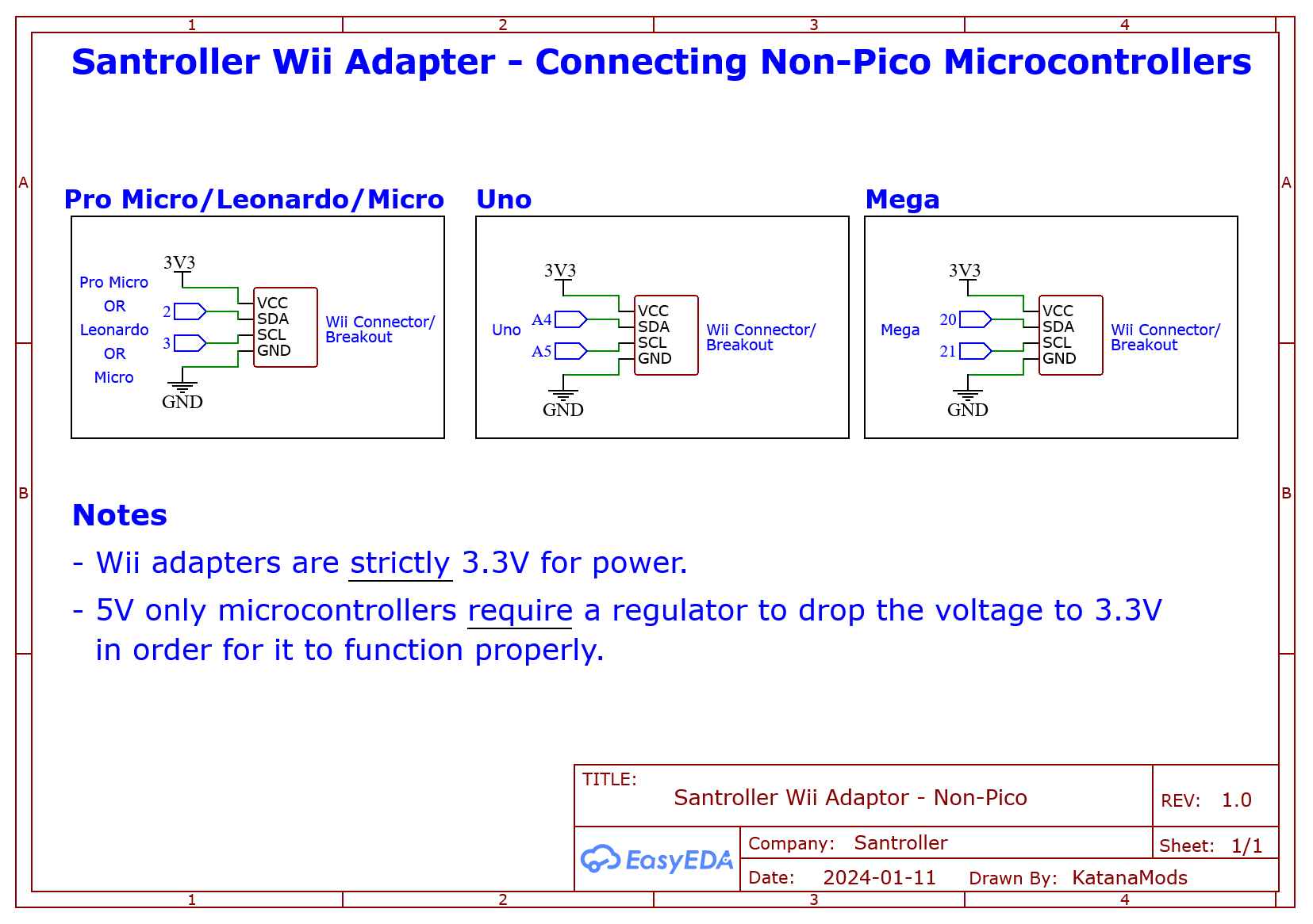
| Pro Micro / Leonardo / Micro | 2 | 3 |
| Uno | A4 | A5 |
| Mega | 20 | 21 |
| Pi Pico (Advanced, Channel 0) | GP0, GP4, GP8, GP12, GP16, GP20 | GP1, GP5, GP9, GP13, GP17, GP21 |
| Pi Pico (Advanced, Channel 1) | GP2, GP6, GP10, GP14, GP18, GP26 | GP3, GP7, GP11, GP15, GP19, GP27 |
2. Connect power (VCC)
- Connect the microcontroller VCC to the breakout VCC
- If using a 5V Pro Micro and a breakout that does not support 5V input, route VCC through a 3.3V regulator
- On the Arduino Uno, use the onboard 3.3V pin
- On the Adafruit breakout:
VINaccepts both 3.3V and 5V input- The
3Vpin is an output and is not required
3. Connect ground
Connect GND on the Wii Extension breakout or cable to GND on the microcontroller.
4. Optional: tilt wiring
Digital tilt
- Connect one pin of the first tilt switch to ground
- Connect the other pin of the first switch to one pin of the second switch
- Connect the remaining pin of the second switch to a digital input on the microcontroller
- Mount the switches on the guitar and adjust placement to control activation angle
Analog tilt
- Connect GND to GND
- Connect VCC to VCC
- Connect the signal pin to an analog input
ADXL345 / MPU-6050 / LIS3DH
- Connect GND to GND
- Connect VCC to 3.3V (use a regulator if required)
- Connect SDA and SCL using the table above
Programming
- Launch Santroller with the microcontroller connected
- Set Connection Method to
Wii Adapter - Set Device to Emulate to the desired controller type
- Click Configure
- If using a Pi Pico with custom pins, set the SDA and SCL pins
- Click Save Settings
Windows controller mode
This setting only affects Windows behavior. Consoles and other operating systems automatically select the correct mode.
-
XInput
- Native Windows support
- Most games auto-bind controls
-
HID
- No automatic binding
- Slightly more efficient polling in games like Clone Hero
Polling and debounce
- Controller Poll Settings allows adjustment of polling behavior
- Queue Based Inputs queues inputs internally and sends them at the USB maximum rate (1 ms)
Poll rate settings:
0sends data as fast as possible- Any other value polls at the specified rate
- DJ Hero turntables must use a poll rate of 10
Debounce:
- Filters noisy button signals
- Prevents dropped sustains caused by button bounce
Combined strum debounce (guitars only):
- Shares debounce timing between strum up and strum down
- Prevents rebound-triggered extra strums
Wii Extension inputs
- Open Wii Extension Inputs
- If using a Pi Pico, specify the SDA and SCL pins
- Click Save
Calibration
Use the Wii Inputs to display below dropdown if multiple devices are connected.
Joysticks / crossfader
- Click Calibrate and move fully left or up
- Click Next and move fully right or down
- Click Next and move slightly off center to set the deadzone
Whammy bar
- Click Calibrate
- Release the whammy and click Next
- Fully press the whammy and click Next
- Release again and click Next
Turntable spin
- Adjust the multiplier if responsiveness is too low
Configuring tilt in Santroller
Ensure you are emulating a guitar, then click Add Setting and add Tilt.
Digital tilt
- Set Input Type to
Digital Pin Input - Set Pin Mode to
Pull Up - Click Find Pin and tilt the guitar
- Enable Invert if using an inverted-output sensor such as some SW520D variants
Analog tilt
- Set Input Type to
Analog Pin Input - Click Find Pin and tilt the guitar
- Click Calibrate
- Tilt down and click Next
- Tilt up and click Next
- Hold the resting position and click Next
Accelerometer-based tilt
- Click Add Setting and add Accelerometer
- Set SDA and SCL pins if using a Pi Pico
- Click Save
- Set Input Type to
Accelerometer Input - Click Calibrate
- Hold the resting position and click Next
- Tilt up and click Next
- Tilt slightly upward and click Next to set the deadzone
- Adjust the Low Pass Filter
- Values near 0 reduce shake sensitivity but lower responsiveness
- Values near 1 increase responsiveness but amplify noise
- A starting value of 0.05 is recommended